Project Description
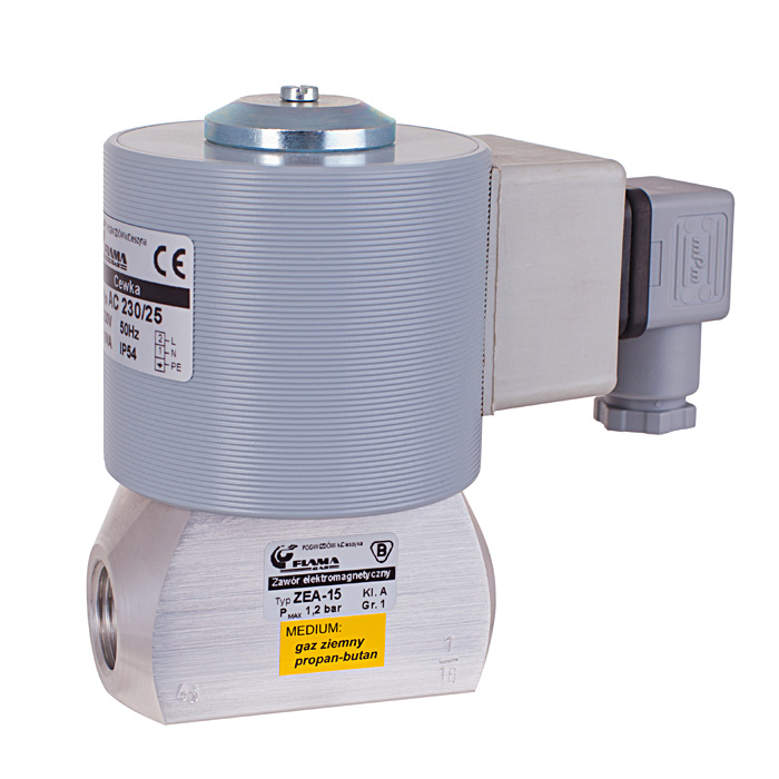
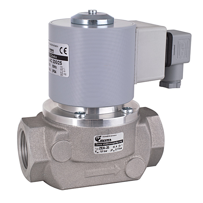
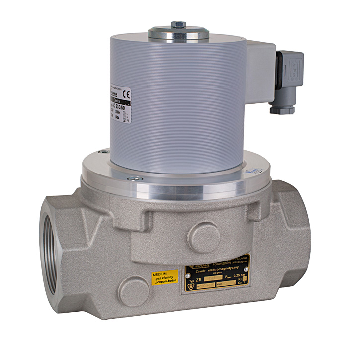
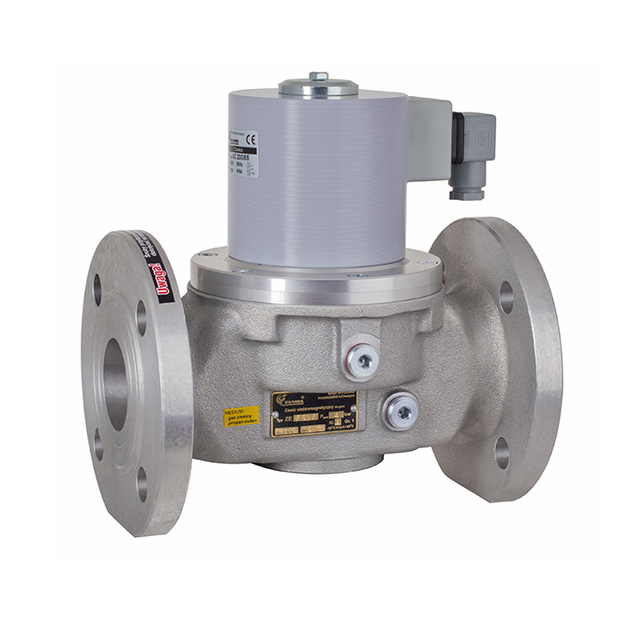
Solenoid valve ZEA
 2/2 NC cl.A
- Fluids: gas fuels, air
- direct acting
- poppet
- manual regulation of flow (option)
- suited to zero pressure differential conditions (ΔPMIN= 0 bar)
- permanent strainer built-in
- conforms to PN-EN161
- designed for reliable service in all types of installations and appliances (e.g burners, heating boilers), supplied from low pressure gas network
- as a part of the gas train supplying gas appliances (mentioned above), the valve will act as an automatic safety shut-off valve acc. to requirements of p 5.2.2.3, PN-EN 746-2 standard
- in air conditioning systems
- pneumatic control systems
| fluid media | gas fuels, air, non-aggressive gases |
| pressure | see tab „Dimensions / Pressures” |
| fluid media temperature | -10°C ÷ +60°C |
| ambient temperature | -10°C ÷ +60°C |
| voltage | AC(50Hz) 24V, 110V, 230V; DC 12V, 24V |
| power | 15W ÷ 71W (depending on type) |
| closing time | <1s |
| flow regulation range | 0% ÷ 100% |
| operation type | continuous (100%) |
| degree of protection | IP54 |
| valve body material | aluminium alloy |
| sealing material | nitrile-butadiene rubber NBR |
| mounting position | coil upwards -acceptable deviation from vertical position up to 90O |
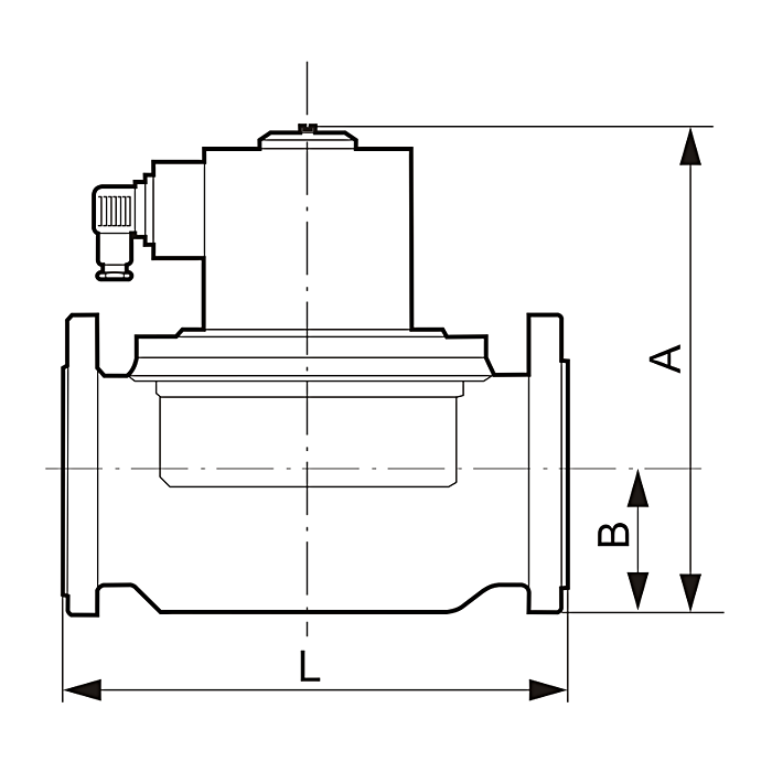
| Type | Dn | Rp | A [mm] |
B [mm] |
E* [mm] |
L [mm] |
PMAX [bar] |
ΔP [bar] |
M [kg] |
|---|---|---|---|---|---|---|---|---|---|
| Threaded connection: | |||||||||
| ZEA-10 | 10 | 3/8 | 109 | 14 | 69/41** | 62 | 1,20 | 0/1,20 | 1,64 |
| ZEA-15 | 15 | 1/2 | 110 | 14 | 69/41** | 72 | 1,20 | 0/1,20 | 1,66 |
| ZEA-20 | 20 | 3/4 | 127 | 22 | 77 | 105 | 0,26 | 0/0,26 | 1,80 |
| ZEA-25 | 25 | 1 | 136 | 28 | 80 | 115 | 0,17 | 0/0,17 | 2,05 |
| ZEA-32 | 32 | 1 1/4 | 174 | 37 | 101 | 145 | 0,14 | 0/0,14 | 4,08 |
| ZEA-40 | 40 | 1 1/2 | 195 | 43 | 110 | 180 | 0,25 | 0/0,25 | 5,80 |
| ZEA-50 | 50 | 2 | 205 | 41 | 140 | 193 | 0,14 | 0/0,14 | 6,40 |
| ZEA-65 | 65 | 2 1/2 | 261 | 61 | 170 | 240 | 0,25 | 0/0,25 | 14,80 |
| Flanged connection: | |||||||||
| ZEA-50k | 50 | 240 | 78 | 165 | 230 | 0,14 | 0,014 | 7,40 | |
| ZEA-65k | 65 | 286 | 83 | 182 | 270 | 0,25 | 0/0,25 | 17,15 | |
| ZEA-80k | 80 | 315 | 94 | 200 | 310 | 0,11 | 0/0,11 | 23,65 | |
| ZEA-100k | 100 | 340 | 103 | 220 | 350 | 0,11 | 0/0,11 | 27,10 | |
** – valve width without coil
• they can operate independently of the existing pressure difference ΔP on the valve
• suited to zero pressure differential conditions (ΔP min= 0 bar)
• their design limitation is the value of the maximum pressure difference ΔPMAX that can occur on the valve. It depends on the lifting force of the electromagnet and the nominal diameter of the valve flow orifice (the larger the nominal diameter, the smaller the ΔPMAX value for the same electromagnet)
• with a pressure greater than the maximum differential pressure ΔPMAX, the valve will not work properly (it will suspend)
• short actuation time (from a dozen to several dozen ms)
• high reliability due to the simplicity of the design and a small number of internal parts
• long lifespan – some designs can reach up to several million work cycles