

1. In terms of mode of operation we divide solenoid valves as follows:
- in the de-energized state normally-Closed Valve (NC)
- in the de-energized state normally-Opened Valve (NO)
2. Due to the specific design features, the solenoid valves produced by us can be divided into 4 characteristic types (groups):
In valves of this type, the force acting on the flow control element (valve head) comes directly from the magnetic field induced by the current flowing in the coil (4). The core (3) of the electromagnet is mechanically fastened to the valve poppet (6) to form a valve head that directly opens or closes the pmain valve flow (2) depending on the presence or absence of the coil supply voltage. This is done without the differential pressure ΔP on the valve. In a de-energized state, when the current through the coil does not flow, the spring (1) presses the poppet (6) with the gasket (6a) to the valve seat (6b) and closes the flow. When the voltage is applied to the coil, the current flowing through it induces a magnetic field that draws the core into the center of the coil. This creates the lifting force of the valve head and open the valve.
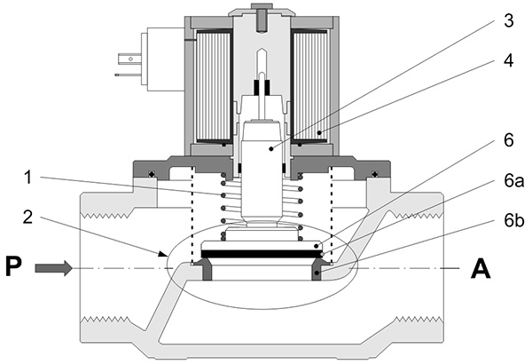
Characteristics:
- design that does not rely on media process pressure or flow
- designed for reliable service regardless of the pressure differential ∆P across the valve
- is suited to zero pressure differential conditions (ΔPMIN = 0)
- their design limitation is the value of the maximum pressure difference ΔPMAX that can occur on the valve. It depends on the lifting force of the electromagnet and the nominal diameter of the valve flow opening (the larger the nominal diameter, the smaller the ΔPMAX value for the same electromagnet)
- may not operate properly if maximum operating differential pressure is exceeded (may jam)
- short response time (from a dozen to several dozen milliseconds)
- excellent reliability due to simple design and relatively small number of moving parts long lifespan up to couple million of cycles for particular designs
Valves of this type utilize the pressure difference across the valve to generate the force required to open the valve and maintain it in the opened state. Pilot actuated valves are composed of two fundamental parts: main-valve (2) and pilot-valve (5). They are equipped in two channels: pilot channel (7) and smaller equalization channel (8). Pilot-valve act as normal direct actuated valve.
In the closed state, the pressure above the membrane (6) (area II) and under the membrane in area I are the same and equal to the inlet pressure P (areas I and II are permanently connected with opened equalization channel (8) and the pilot channel (7 ) is closed). When the voltage is applied to the coil (4), the pilot valve (5) opens and the pilot channel (7) opens. The existing pressure difference between the area II above the membrane and the area III on the discharge side A causes the medium to pass through the pilot channel. As the flow through the pilot channel (7) is larger than through the equalizing channel (8), the pressure in area II above the membrane starts to decrease. The resulting differential pressure ΔP on the membrane, between area I on the inlet side and area II above the membrane, will create a force that overcomes the pressure of the pressing spring (1) and lift the membrane (valve) and open the main valve (2). This force will keep the valve head in the open position.
Closing the pilot valve (after voltage decay on the coil) stops the medium flow through the pilot channel (7). Due to the still existing flow through the equalizing channel (8), the pressure in area II above the membrane begins to increase. When it balances (together with the spring) the pressure under the membrane (on the inlet side) – the main valve (2) will start to close.
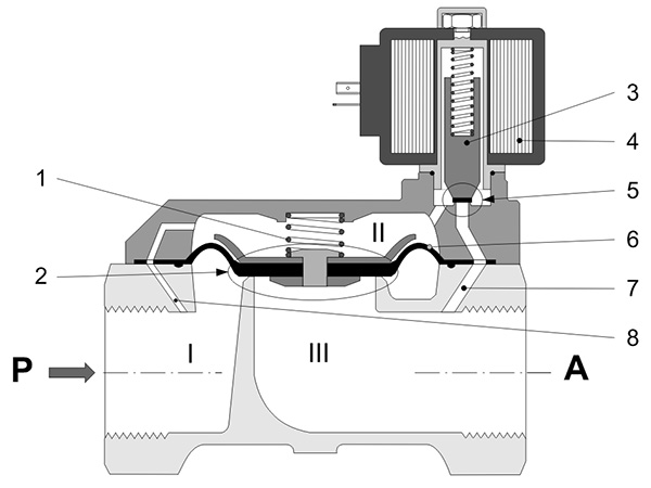
Characteristics:
- use process pressure for operation
- work correctly only if there is a required minimum differential pressure ΔPMIN on the valve. In case it is smaller than required, valves of this type will not work properly.
- pressure difference ΔP is needed to open the valve and keep it in the open position,
- the speed of opening and closing the valve depends on the size of this difference
- due to the small cross-sections of control channels they are sensitive to contamination (use appropriate filters upstream of them)
- long activation time (in some types even up to several seconds)
- lower lifespan (on average – several hundred thousand work cycles)
In many installations, it is difficult to determine what the minimum pressure difference ΔPMIN will be on the valve. Therefore, it is necessary to use universal valves that work independently of the pressure difference. These are valves with assisted lift.The construction of such a valve is similar to an intermediate operation valve, with the difference that the pilot valve (5) is located in the main valve poppet (2). The valve head (membrane) of the main valve (2) is lifted by the movable core (3) (valve head of the pilot valve (5)) by means of an elastic system, i.e. allowing first full open of the pilot-valve seat (direct action).The space II above the membrane (6) is connected to the area I from the inflow side P by a permanently open equalization channel (8). The pilot valve (5) connects through the pilot channel (7) area II above the membrane with the area III from the outflow side A. When the valve is closed, the pilot channel is also closed. The pressure above the membrane is equal to the pressure on the inlet side.At low or zero pressure difference ΔP, the valve works like a direct-acting valve. The force lifting the core after applying the voltage to the coil (4), simultaneously opens the pilot valve (5) and the main valve (2). The closing of both valves takes place under the influence of the spring (1) after the current decay in the coil (4).When the pressure difference ΔP is large, the valve works as an intermediate valve. Applying voltage to the coil causes the pilot valve (5) to open. The area II is connected over the membrane to the area III from the outflow side. The pressure above the membrane drops, the main valve (2) opens due to the differential pressure ΔP, which keeps it in the open position.The decay of current in the coil forces the pilot valve to close. The pressure above the membrane is rising. The force balancing the force from the pressure difference ΔP on the valve appears. The valve closes.
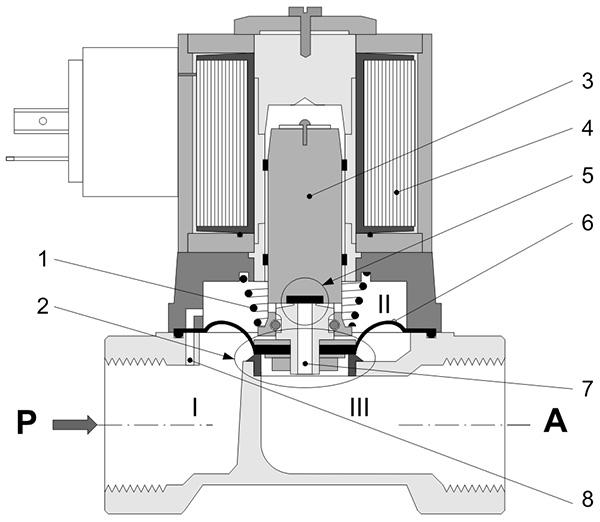
Characteristics
- they are used in systems where the pressure difference ΔP on the valve is variable or difficult to determine
- they work properly regardless of the differential pressure ΔP on the valve – although they use process pressure for operation
- they can be used from zero to the maximum PMAX operation pressure to which they have been designed
- have relatively high flow resistance (low Kv coefficient) – design aspects
- they are sensitive to contamination – proper cleanliness of the medium should be ensured (use filters)
- long response times – low connection frequency
- lifespan – less than direct action valves (several hundred thousand work cycles)
The design of these valves and the way they work are related to the function they perform in cooperating with gas detectors (detection systems).The following elements can be distinguished in these valves:
- element enabling manual opening (eg handle (3))
- valve head (3a, 6, 6a) manually driven and locked in the open position by a ratchet mechanism (5)
- main valve (2)
- electromagnetic trigger (4)
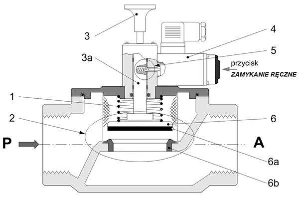
Valves of this type can only be opened manually.By pulling the manual valve opening handle (3) valve head is moving until it is locked by ratchet mechanism (5) in the fully open position. This is the valve’s operating position – gas can flow freely through the valve.Releasing the lock, and thus immediate closing of the valve, can take place in two ways:
- an electric impulse supplied (eg from a gas detector) to an solenoid trigger coil (4) causes the movement of its core, which by acting on the ratchet mechanism (5) releases the blockade of the valve head. The valve head under the influence of the pressing spring (1) goes into the closed position. The gas flow is cut off by the mechanical pressure of the poppet (6) together with the gasket (6a) to the valve seat (6b) caused by the pressing spring.
- by pressing the “MANUAL CLOSE” button, we force mechanically the movement of the solenoid trigger core, thus causing the release of the valve head lock and closing of the valve.
Characteristics:
- in both open and closed positions they do not require power supply – they are energy-saving (electrical impulse with duration <1s is only needed to close the valve)
- insensitive to the loss of voltage supply – its absence or temporary fading does not cause changes in the gas flow through the valve
- resistant to any interferences that in the closed state may cause its accidental opening (only conscious actions of supervising personnel)
- very small maneuvering space required to operate and low force needed to open the valve
- simple, cheap, reliable and light construction
- long lifespan